
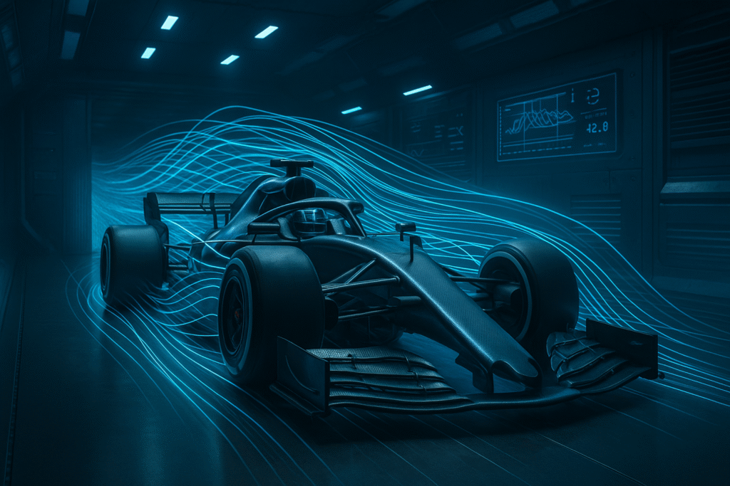
The Essential Role of Wind Tunnels in Formula 1: A Deep Dive into Aerodynamic Mastery
Table of Contents
- Introduction
- Why Wind Tunnel Testing is Essential in Formula 1
- How Wind Tunnels Work
- Key Components of a Wind Tunnel
- Challenges in Wind Tunnel Design and Operation
- The Impact of Regulations on Wind Tunnel Usage
- Wind Tunnels vs. Computational Fluid Dynamics (CFD)
- Future Innovations in Wind Tunnel Technology
- Conclusion
Introduction: The Critical Role of Wind Tunnels in Formula 1 Aerodynamics

In the relentless pursuit of performance within Formula 1, aerodynamics has evolved into the single most influential variable in lap time optimization. While power unit development and mechanical grip remain important, it is aerodynamic efficiency—the ability to maximize downforce with minimal drag penalty—that separates championship contenders from midfield runners.
At the core of this aerodynamic refinement lies an indispensable tool: the wind tunnel.
Despite the growing sophistication of Computational Fluid Dynamics (CFD), wind tunnel testing continues to serve as the ground truth in aerodynamic validation. This is not merely for historical inertia or habit, but due to the inherent limitations in turbulence modeling, Reynolds scaling fidelity, and coupled thermal-fluid simulations in CFD, particularly when applied to transitional flow regimes, rotating wheels, and complex bodywork interactions.
Wind tunnels offer a controlled, repeatable environment where 60%-scale models, rotating wheels, active rake sensors, and pressure taps can be used to extract real-time flow data with high spatial and temporal resolution. These models can be subjected to yaw sweeps, pitch adjustments, and ride height variations that simulate a range of cornering and braking scenarios with aerodynamic repeatability that CFD alone cannot achieve.
What This Guide Will Cover
This in-depth article explores:
-
-
How wind tunnels work in the context of F1, including test section design, boundary layer control, and force measurement systems
-
Scaling laws and model fidelity, including Reynolds number distortion, Mach effects, and fan turbulence intensity
-
Instrumentation: Multi-axis balances, PIV (Particle Image Velocimetry), rakes, and tuft visualization
-
Interaction with CFD: How wind tunnel data is used to calibrate and correct computational simulations
-
Regulatory limitations imposed by the FIA under the Aerodynamic Testing Restrictions (ATR) framework
-
Trends for the future: including hybrid simulation approaches and virtual wind tunnel environments
-
Key Takeaways for Advanced Readers
-
-
Wind tunnels remain essential for experimental validation of CFD-derived flow fields, particularly in unsteady, rotating, and transitional flow regimes
-
Model testing allows for detailed control over AoA (angle of attack), pitch/yaw sweeps, ride height, wheel rotation, and steering input
-
Regulations enforce strict limits on tunnel hours, run configurations, and model scale, creating a strategic trade-off between physical fidelity and development allocation
-
The future points toward a hybrid testing paradigm, where CFD and wind tunnel outputs are statistically reconciled through Machine Learning (ML) models and surrogate-based optimization frameworks
-
In this guide, we won’t just explain what wind tunnels are—we’ll explore how they serve as the aerodynamic backbone of F1 engineering, and why, in the most computationally advanced sport on earth, nothing replaces data grounded in the wind.
Why Wind Tunnel Testing Is Essential in Formula 1

In the context of modern Formula 1, where aerodynamic sensitivity, flow stability, and surface interaction effects define competitive performance, wind tunnel testing remains a non-negotiable pillar of vehicle development. While CFD provides insight into flow fields and trends, only wind tunnel testing offers high-fidelity, repeatable, and directly measurable aerodynamic data in a controlled physical environment.
Here’s why wind tunnel testing continues to be indispensable at the elite level of motorsport:
1. High-Fidelity Aerodynamic Evaluation Under Controlled Conditions
Wind tunnels allow engineers to test scaled models (typically at 60%) in controlled flow conditions, enabling precise characterization of:
-
-
Global forces (lift/downforce, drag, side force)
-
Moment coefficients (yaw, pitch, roll)
-
Local flow behavior using rakes, pitot arrays, and tufts
-
Unlike on-track testing, environmental variables such as wind, temperature, and turbulence intensity are eliminated, allowing engineers to isolate the aerodynamic influence of specific geometries.
Furthermore, wind tunnels can simulate ride height sweeps, yaw angles, and pitch conditions that replicate various cornering and braking scenarios — including nonlinear flow regimes and ground effect behavior, which are difficult to model accurately in CFD due to turbulence closure limitations.
2. Drag-Downforce Trade-Off Optimization
Maximizing aerodynamic efficiency (defined as the ratio L\D requires a delicate balance between:
-
-
Induced drag reduction through wing profile optimization
-
Downforce generation via diffusers, underfloor geometry, and vortex management
-
Pressure recovery in wake zones and around complex structures (e.g. bargeboards, turning vanes)
-
Wind tunnels allow engineers to conduct parametric studies and design of experiments (DoE) on aero appendages, analyzing the direct impact on lift coefficients, boundary layer stability, and vortex shedding behavior — all of which are essential to track performance.
3. Thermal Management and Cooling Aerodynamics
Thermal loads in modern F1 cars are substantial — driven by hybrid power units, energy recovery systems (ERS), and tight packaging. Wind tunnel testing enables:
-
-
Evaluation of duct efficiency and pressure drop across radiators
-
Analysis of mass flow rate through sidepods and cooling inlets
-
Detection of flow separation and recirculation zones around heat exchangers
-
This is particularly critical in transient operating conditions (e.g. during braking or coasting), where cooling performance must remain stable without compromising external aerodynamics.
4. CFD Validation and Model Correlation
Wind tunnel data provides the reference baseline against which CFD models are calibrated and validated. Key correlations include:
-
-
Surface pressure distribution
-
Velocity profiles at boundary layer probes
-
Wake structure coherence and turbulence intensity downstream of the car
-
Discrepancies between CFD and wind tunnel results often highlight numerical diffusion, mesh resolution limits, or inadequate turbulence models, especially in areas involving rotating reference frames (RRF) for wheel modeling or moving floor simulations.
This process — known as model correlation and correction — is vital to ensure that CFD predictions are not only computationally accurate but physically representative.
5. Regulatory Compliance and Performance Exploitation
The FIA Aerodynamic Testing Restrictions (ATR) impose strict limitations on wind tunnel usage:
-
-
Fixed model scale (60%)
-
Capped wind-on hours per aerodynamic testing period
-
Restrictions on mass flow rates, yaw angles, and moving ground systems
-
Wind tunnel testing thus becomes a strategically optimized resource, where teams must extract maximum aero insight per testing hour. It is also essential for ensuring that design modifications remain compliant with FIA bodywork templates, wake regulation zones, and visibility rules — particularly in regions like the front wing, floor edge, diffuser, and beam wing.
Summary for Advanced Readers
Wind tunnel testing is not simply about “seeing if a part works.” It is a core method of experimental aerodynamics, rooted in:
-
-
Navier-Stokes simplification for physical scale modeling
-
Dimensional analysis and Reynolds/Mach scaling trade-offs
-
Real-time measurement of complex 3D flow interactions under repeatable and instrumented conditions
-
In the hybrid development environment of modern F1, wind tunnels serve as the empirical anchor point—the reference by which all virtual models must align.
How Wind Tunnels Work in Formula 1
Wind tunnel testing in Formula 1 involves much more than blowing air at a scale model. It’s a precise aerodynamic laboratory where physical fidelity, flow control, and data resolution are pushed to the limits of experimental engineering.
At the heart of this process is a closed-loop, low-turbulence wind tunnel capable of simulating key aerodynamic parameters such as ride height, yaw, wheel rotation, and ground effect.

Step-by-Step: Technical Workflow
1. Model Preparation
-
-
Models are typically built at 60% scale, per FIA regulations, with exacting geometric fidelity.
-
Components are modular and interchangeable to allow A/B testing (e.g., front wing versions, floor strakes).
-
Built using composite structures to resist aero loads without deformation.
-
Embedded with:
-
Pressure taps for surface Cp measurements
-
Optical tracking markers for deformation study
-
Ports for PIV and tuft flow visualization
-
-
2. Mounting on a Rolling Road
-
-
The model is mounted over a rolling belt system that simulates track-relative ground speed.
-
This moving floor replicates the ground effect environment (critical for underfloor flow accuracy).
-
The car sits on a 6-component balance, allowing high-precision measurement of:
-

3. Generating Controlled Airflow
-
-
High-power axial fans (often >500 kW) generate speeds of up to 50 m/s (180 km/h).
-
Flow conditioning includes:
-
Honeycomb flow straighteners
-
Screens and contraction cones to reduce turbulence intensity
-
Optional active grids to simulate gusts or turbulent inflow
-
-
Tests include:
-
Yaw sweeps (±15°)
-
Ride height ramps
-
Simulations of braking pitch or acceleration squat
-
-
4. Measurement and Instrumentation
Wind tunnels use an array of tools to capture the aerodynamic behavior in real-time:
| Instrument | Purpose |
|---|---|
| Pressure taps | Surface pressure coefficient (Cp) distributions |
| Rakes | Wake velocity profile measurement (Pitot + static) |
| PIV (Particle Image Velocimetry) | Full-field flow visualization with high spatial resolution |
| Tufts & smoke wires | Qualitative flow visualization |
| Infrared thermography | Surface heating/cooling patterns (for cooling studies) |
Data acquisition systems sample force and moment signals at high frequency (>1kHz) and integrate with model kinematics.
5. Data Reduction and Flow Analysis
Engineers evaluate results using normalized coefficients:

Key analysis tasks include:
-
-
Optimization of pressure recovery zones
-
Minimizing separation zones at key flow interfaces (e.g., floor edge, rear wing wake)
-
Wake footprint analysis for drag signature
-
Alignment with CFD to reconcile Reynolds number discrepancies and mesh artifacts
-
Example Data: Force vs Wind Speed
From a typical wind tunnel test session using a 60% model:
| Wind Speed (m/s) | Drag Force (N) | Downforce (N) |
|---|---|---|
| 20 | 180 | 250 |
| 30 | 405 | 590 |
| 40 | 720 | 980 |
| 50 | 1125 | 1450 |
Note how aerodynamic forces scale quadratically with wind speed, as governed by:

Why This Matters
The goal isn’t just to validate concepts — it’s to extract precise, scalable aerodynamic coefficients under controlled, high-fidelity conditions. Despite CFD advancements, real-world flow interactions like vortex breakdown, tire wake, underfloor suction, and high-yaw flow attachment still require physical validation.
Types of Wind Tunnels in Formula 1 and High-Performance Aerodynamics
Wind tunnels come in a variety of configurations, each designed to simulate specific flow regimes and physical constraints. In the context of Formula 1, where subsonic, low-turbulence, and high-fidelity flow simulation is critical, teams employ highly specialized tunnel types tailored for vehicle-scale aerodynamic testing.
Understanding the different wind tunnel architectures is essential for interpreting experimental reliability, flow conditioning quality, and scaling accuracy.

1. Open-Return vs. Closed-Return Tunnels
Open-Return (Eiffel-Type)
-
-
Air is drawn in from the ambient environment and exhausted back into it.
-
Inexpensive and easy to construct.
-
Major drawbacks:
-
Susceptible to external environmental fluctuations (temperature, humidity, wind).
-
Higher turbulence intensity (>1.5%).
-
Poor energy efficiency.
-
-
Rarely used in professional motorsport, mostly for academic or conceptual testing.
-
Closed-Return (Göttingen-Type)
-
-
Air circulates within a sealed duct loop, maintaining a consistent and conditioned flow environment.
-
Integrated with:
-
Honeycomb straighteners
-
Flow conditioning screens
-
Temperature control systems
-
-
Advantages:
-
Turbulence intensity < 0.5%.
-
Superior flow uniformity and repeatability.
-
Thermally stable—ideal for correlation with CFD.
-
-
Standard in Formula 1, used by teams such as Mercedes-AMG F1 (Brackley) and Red Bull Racing (Bedford).
-
2. Steady-State vs. Blow-Down Wind Tunnels
Steady-State Tunnels
-
-
Use electric fans to maintain continuous, controlled airflow.
-
Ideal for low-speed, steady flow applications (Mach < 0.3).
-
Allow long-duration testing with real-time data acquisition and live model adjustments.
-
Blow-Down Tunnels
-
-
Operate via compressed air reservoirs, releasing high-pressure air through a test section in short bursts.
-
Used in aerospace and transonic/supersonic studies.
-
Not used in F1, where continuous subsonic flow is essential.
-
3. Moving Ground Tunnels (Rolling Road Simulation)
For vehicles operating near the ground—such as F1 cars, LMP1 prototypes, and performance road cars—accurately modeling the relative motion between the car and the ground plane is essential. Standard fixed-floor tunnels introduce a boundary layer mismatch, leading to significant errors in underbody flow simulation.
Moving Ground Wind Tunnels:
-
-
Feature a rolling belt under the car model, synchronized with airflow velocity.
-
Include rotating wheel rigs, simulating wheel rotation and wake shedding.
-
Boundary layer suction systems are used to eliminate velocity deficits near the belt surface.
-
Some facilities use multi-belt systems to separately simulate the motion of all four wheels + central floor.
-
These systems are essential for replicating ground effect behavior, diffuser expansion, and underfloor pressure gradients with high accuracy. FIA mandates moving ground simulation for all team wind tunnels.
4. Other Classifications
| Category | Examples | Use in F1 |
|---|---|---|
| Low-Speed, Subsonic | < Mach 0.3; Used for most car testing | ✅ Standard |
| Transonic / Supersonic | Aerospace, not relevant to F1 | ❌ Not used |
| Vertical Wind Tunnels | Skydiving/bodyflight | ❌ Not relevant |
| Thermal / Climatic Tunnels | Simulate heat flux and snow/water intrusion | ❌ Not used in F1 |
| Full-Scale Automotive Tunnels | Used in road car development (e.g. Mercedes, BMW, Audi) | 🔁 Indirect application for road-derived GT cars |
Summary: What F1 Teams Use Today
Modern F1 teams use closed-return, low-speed, moving ground wind tunnels with the following specifications:
-
-
60% scale model (FIA mandated)
-
Rolling road with belt speeds up to 50 m/s (180 km/h)
-
Yaw sweep capability (±15°)
-
Low turbulence intensity (<0.5%)
-
6-component force balances
-
Full integration with CFD and simulation workflows
-
This configuration represents the optimal balance between experimental control, scalability, and regulatory compliance, and is critical for validating vortex dynamics, underbody suction, cooling performance, and wake behavior in current F1 regulations.
Challenges in Wind Tunnel Design and Operation
While wind tunnels remain indispensable for aerodynamic development, their implementation in Formula 1 is accompanied by a host of technical, logistical, and regulatory constraints. These limitations influence everything from design fidelity to data reliability, requiring aerodynamicists to constantly navigate trade-offs between cost, accuracy, and efficiency.
Below are the most critical challenges associated with wind tunnel use in F1:
1. Capital and Operational Cost
Constructing and operating a high-fidelity, FIA-compliant wind tunnel involves substantial investment. Modern facilities typically require:
-
-
Multi-megawatt fan arrays
-
Rolling road systems with low boundary layer interference
-
Climate control systems to maintain isothermal conditions
-
Vibration-isolated test platforms
-
PIV-capable optical access and safety shielding
-
Estimated costs range from $40–100 million USD for construction, with annual operation/maintenance often exceeding $2–5 million.
Only factory-supported manufacturers (e.g., Ferrari, Mercedes, Red Bull) maintain full in-house facilities. Smaller teams often rely on shared access or third-party tunnels (e.g., Toyota’s Cologne facility).
2. Spatial and Mechanical Constraints
A wind tunnel’s test section must simulate dynamic vehicle conditions within the boundaries of a confined physical envelope:
-
-
Model size is fixed at 60% scale (FIA-mandated), introducing Reynolds number distortion due to lower dynamic similarity.
-
Rolling road belts have finite length and width, limiting test repeatability for extreme yaw or ride height conditions.
-
Fan pressure gradients and boundary interference can cause flow non-uniformity, especially near the test section walls or tunnel exits.
-
Additionally, teams must account for:
-
-
Wall interference corrections
-
Turbulence decay zones
-
Blockage effects in high-AoA configurations
-
3. FIA Regulation Limits (ATR Framework)
The Aerodynamic Testing Restrictions (ATR) impose strict usage caps on wind tunnels to contain development arms races. Under current rules (as of 2023–2026 regulation cycle):
-
-
Model scale: Limited to 60%
-
Maximum wind-on time: 400 hours/year (varies by championship position)
-
Run configurations: Restrictions on component testing combinations
-
Moving ground speed: Capped to match full-scale Reynolds similarity within allowable power limits
-
Flow conditioning: Cannot simulate environmental transients (e.g., crosswinds, humidity)
-
These limits force teams to prioritize testing windows carefully and emphasize CFD-WT correlation efficiency over brute-force iteration.
4. Correlation and Fidelity Challenges
One of the most significant engineering challenges is achieving accurate correlation between wind tunnel results, CFD predictions, and on-track data.
Key correlation issues include:
| Source of Deviation | Description |
|---|---|
| Reynolds scaling | Scale models operate at lower Reynolds numbers, affecting boundary layer transition and separation behavior. |
| Track-specific transients | Real-world air density, crosswind shear, tire deformation, and transient yaw are difficult to replicate in tunnel conditions. |
| Thermal effects | Wind tunnels typically operate isothermally, ignoring thermal stratification around the power unit and brakes. |
| Mechanical deformations | On-track aerodynamic surfaces (e.g., floor edges, endplates) deform under load — not captured on rigid scale models. |
| Tire dynamics | Rotating wheels in tunnels cannot fully replicate slip angle, lateral force buildup, or tread deformation seen in real conditions. |
To mitigate this, teams use Data Fusion techniques, including:
-
-
CFD–WT hybrid models
-
Surrogate modeling
-
Statistical regression to quantify track-to-tunnel deltas
-
The Impact of Regulations on Wind Tunnel Usage
In an effort to maintain sporting equity and reduce the technological arms race driven by budget asymmetry, the FIA introduced the Aerodynamic Testing Restrictions (ATR) framework — a set of codified rules that govern and limit the scope of aerodynamic development, both physically (wind tunnels) and virtually (CFD).
This regulation is not merely administrative — it has reshaped how teams approach aerodynamic optimization, forcing them to extract maximum aerodynamic value under constrained experimental bandwidth.
Goals of the ATR System
-
-
Level the playing field: Prevent dominant teams from relying on resource brute-force.
-
Encourage innovation under constraint: Success now hinges on engineering efficiency rather than test volume.
-
Promote competitive balance: Lower-ranked teams are granted development advantages to accelerate convergence.
-
Current ATR Framework (2024 Season)
The ATR system regulates both wind tunnel testing (WT) and computational fluid dynamics (CFD) through a weighted allocation tied to Constructors’ Championship position in rolling 6-month windows.
| Team Ranking (Championship) | Wind Tunnel Time Allowed | CFD Grid Allowance |
|---|---|---|
| P1 (1st place) | 70% baseline | 70% baseline |
| P5 | 100% baseline | 100% baseline |
| P10 (last place) | 115% baseline | 115% baseline |
The baseline is defined as 320 runs or 400 hours per year at 60% scale. A team in P1 would be limited to ~280 runs, while P10 may exceed 460.
Specific Technical Restrictions
| Parameter | Limit |
|---|---|
| Model Scale | Max 60% |
| Max Wind Speed | 50 m/s |
| Test Duration | Limited to wind-on time only (airflow active) |
| Yaw Sweep Range | ±15° |
| Moving Ground Belt Width | ≥0.9 × track width (per FIA spec) |
| Data Capture Frequency | Max 1 Hz per parameter unless otherwise approved |
Teams are also restricted in:
-
-
How many geometries can be tested per week
-
What kinds of flow visualization methods can be used (e.g., restricted smoke or dye injection)
-
CAD update frequency across CFD and tunnel platforms (to prevent iteration spamming)
-
Strategic Consequences of the ATR
The ATR forces teams to:
-
-
Prioritize high-value development paths using sensitivity maps, design of experiments (DoE), and adjoint optimization.
-
Develop strong CFD–WT correlation protocols to reduce dependency on repeated physical runs.
-
Leverage AI/ML surrogate models to simulate hundreds of variations virtually, then only test the most promising in the tunnel.
-
Smaller teams benefit by increasing their WT/CFD cycles, allowing them to catch up or explore more design permutations.
The Result: Innovation Under Constraint
The net effect of ATR is to transform aerodynamic development into a problem of constrained optimization, where teams must:
-
-
Identify the most sensitive regions of the car to improve (e.g. floor edges, diffuser throat, wake management)
-
Use data fusion techniques to unify experimental and simulation pipelines
-
Schedule wind tunnel runs in concert with CFD convergence cycles and track data calibration
-
Success is no longer determined by who tests more — it’s determined by who tests smarter.
Wind Tunnels vs. Computational Fluid Dynamics (CFD)
The question of whether wind tunnels will become obsolete in the face of increasingly sophisticated CFD (Computational Fluid Dynamics) tools is often raised — and often oversimplified.
In reality, CFD and wind tunnels are complementary, not competitive. Each method offers unique advantages and inherent limitations, and the most successful aerodynamic programs in F1 integrate both within tightly coupled, correlation-driven workflows.

| Aspect | Wind Tunnel | CFD Simulation |
|---|---|---|
| Physical Fidelity | Captures full 3D flow physics (incl. vortex breakdown, underfloor flow) | Approximates flow using turbulence models (e.g., RANS, LES) |
| Scalability | Limited by model size (60%) and physical constraints | Unlimited geometry iteration and transient modeling |
| Cost | High CAPEX + OPEX (energy, technicians, hardware) | Lower operational cost but requires HPC infrastructure |
| Time-to-Insight | Physical setup + flow stabilization takes hours | Parallel simulations deliver multiple cases per day |
| Turbulence Accuracy | Real-world turbulence captured naturally | Depends on turbulence closure (e.g., k-ε, SST, DES) |
| Boundary Conditions | Realistic tire/wheel/ride height interaction | Boundary assumptions may oversimplify motion/thermal coupling |
In practice, wind tunnels validate CFD predictions, while CFD expands the design envelope between test windows.
Future Innovations in Wind Tunnel Technology
To remain viable and relevant in an increasingly simulation-heavy development cycle, wind tunnel technology is undergoing a silent revolution, blending experimental precision with computational intelligence.

1. AI-Powered Aerodynamic Optimization
Teams are integrating machine learning algorithms (e.g., genetic algorithms, Bayesian optimization, surrogate modeling) to:
-
-
Guide design space exploration
-
Predict sensitivity to geometric changes
-
Optimize test matrix coverage within limited ATR budgets
-
ML agents are now capable of evaluating millions of CFD simulations to suggest physical geometries for maximum efficiency per tunnel run.
2. Advanced Sensing and Flow Visualization
New generations of non-intrusive diagnostics are improving data precision and resolution:
-
-
Time-resolved PIV (Particle Image Velocimetry)
-
Laser Doppler Anemometry (LDA)
-
Infrared thermography for cooling validation
-
Optical deformation tracking of flexible aero surfaces
-
These systems yield full-field vector maps of flow velocities, vorticity, and boundary layer dynamics — particularly useful for underfloor and wake regions.
3. Sustainable Tunnel Operation
With rising environmental awareness and energy costs, teams are retrofitting tunnels with:
-
-
Variable-speed fans for load-matched testing
-
Heat exchangers and thermal recovery systems
-
Solar and wind energy integration to offset grid consumption
-
This aligns with F1’s broader Net-Zero Carbon strategy while preserving the fidelity of high-end aerodynamic testing.
4. The Rise of Virtual Wind Tunnels
Hybrid workflows are emerging that blend real-time wind tunnel feedback with CFD prediction layers, enabling:
-
-
Dynamic geometry adjustment during test campaigns
-
Live comparison of predicted vs. measured Cp plots
-
AI-guided refinement loops between physical and digital tests
-
These “virtual twin” systems are redefining the way experimental data is interpreted and used to close the CFD–WT–Track loop.
Conclusion: The Irreplaceable Role of Wind Tunnels in F1
Despite the rise of computational tools, wind tunnels remain the aerodynamic backbone of Formula 1 engineering. Their ability to provide high-resolution, real-world, multi-dimensional flow data under controlled and repeatable conditions cannot yet be matched by simulation alone.
As teams operate under strict ATR constraints, success depends not on the volume of testing, but on the intelligence of test design, simulation integration, and insight extraction. Wind tunnels, enhanced by AI and advanced diagnostics, will remain critical to that mission.
Key Takeaways
Wind tunnels offer physical validation of aerodynamic performance, especially in high-complexity flow regimes.
CFD provides broad exploration, but still requires empirical anchoring via wind tunnel data.
FIA regulations limit wind tunnel use — demanding smarter, not more, testing.
Future wind tunnel systems will be smarter, greener, and tightly integrated with simulation and AI tools.

